

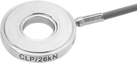
IDS-E-Line Indirect Cavity Pressure Sensors 3 ... 36 mm | 3 ... 80 kN
Compatible accessories
Standard accessories
Integration with your molding line
Specifications & docs
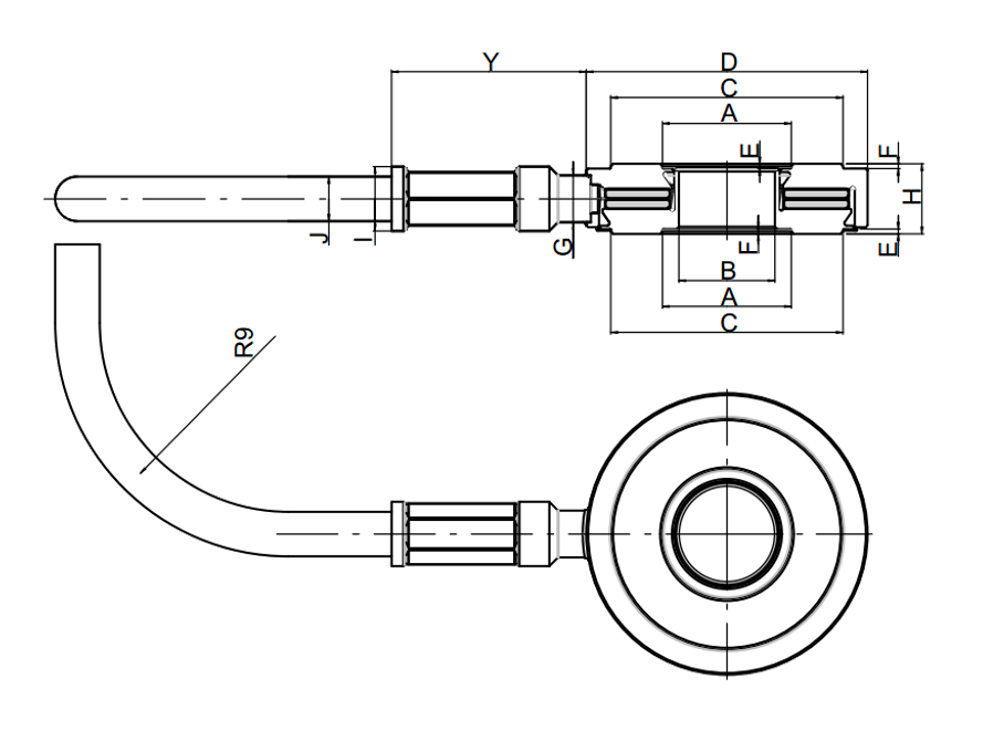
Type | A | B | C | D | E | F | G | H | I | J | Y
IDS-E-3 | 4.05 | 2.7H7 | 6.5 | 8-0.05 | 0.12 | 0.15 | 2 | 3-0.05 | ~2.7 | 1.9 | ~8.3
IDS-E-7 | 5.5 | 4.1H7 | 9.9 | 12±0.05 | 0.2 | 0.2 | 2 | 3-0.05 | ~2.7 | 1.9 | ~8.3
IDS-E-14 | 7.8 | 6.1H7 | 13.9 | 16-0.05 | 0.29 | 0.32 | 2 | 3.5-0.05 | ~2.7 | 1.9 | ~8.3
IDS-E-26 | 9.8 | 8.1H7 | 17.9 | 20-0.05 | 0.3 | 0.32 | 2 | 3.5-0.05 | ~2.7 | 1.9 | ~8.3
IDS-E-36 | 11.8 | 10.1H7 | 21.9 | 24-0.05 | 0.29 | 0.32 | 2 | 3.5-0.05 | ~2.7 | 1.9 | ~8.3
IDS-E-62 | 13.8 | 12.1H7 | 27.9 | 30-0.05 | 0.5 | 0.45 | 2 | 4-0.05 | ~2.7 | 1.9 | ~8.3
IDS-E-80 | 15.8 | 14.1H7 | 33.9 | 36-0.05 | 0.52 | 0.52 | 2 | 5-0.05 | ~2.7 | 1.9 | ~8.3
Values are in [mm].
Please refer to the technical drawing attached above in the image section for the definition and location of dimensions A, B, C, D... shown in the table.
Key Features
- Indirect Cavity Pressure Measurement via Force on Ejector Pins
- Nominal Force Range from 3 kN to 80 kN
- Operating Temperature Range up to 120°C
- Extremely Flat, Symmetrical Design for Easy Integration
- Integrated Charge Cable for Robust Connection
- Ideal for Molds with Limited Space or Complex Geometries
- Connector Type: 10-32UNF
Sensor Type
Indirect
Operating Principle
Piezoelectric, Charge Output
Sensing Element
Quartz
Dynamic Measuring Range
0 … 3 to 80 kN (model dependent)
Limit Force
150 % of Fnom
Sensitivity (typical)
4.3 pC/N
Linearity
≤ ± 1 % FSO
Operating Temperature Range
-20 … +120 °C
Internal Isolation Resistance
> 10¹³ Ohm (25 °C)
Protection Class
IP65
Datasheet:
IDS-E_Line.pdf